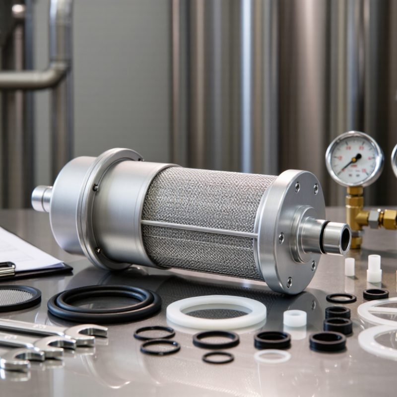
Buying the right Ts Filter isn't usually just about picking the finest mesh. I mean, real performance comes down to flow rate, pressure, fluid temperature, and whether the materials actually play nice together. A filter can look great on paper and still clog up fast on a busy production line. And when that happens? You get downtime, wasted product, and maintenance costs you really didn't need.
Dr. Elena Marquez, a filtration engineer with over 15 years of industrial consulting experience, puts it simply: 'Filtration decisions should begin with the process, not the product.' That's practical advice. Measure your operating conditions before you start comparing brands. Check the stated micron rating. Confirm the actual flow capacity. Look at housing materials, seals, cleaning needs, and whether replacements are easy to get. These things often matter way more than a low purchase price.
Small details matter. A lot.
This guide walks through seven practical tips for buying the right Ts Filter. We'll look at how to match filtration accuracy to real operating needs, compare pressure loss, and figure out whether stainless steel, polypropylene, or something else fits your application. We'll also touch on supplier documentation, testing standards, service support, and total ownership cost.
Some of these recommendations might seem obvious. They're still easy to miss. I've seen buyers fixate on particle size while ignoring viscosity and temperature. At first, that choice looked reasonable—but the filter blocked much earlier than expected. No filter is perfect. The right call comes from balancing protection, capacity, maintenance, and budget. A careful review before you buy can save you from an expensive fix later.
Buying the right TS Filter starts with a measurable wavelength target. Do not rely on the label alone. Ask for the center wavelength, passband, blocking range, and transmission curve.
CIE 018:2019 places peak human photopic sensitivity near 555 nm, but your detector may respond strongly outside that point. A laboratory camera, fluorescence sensor, and laser alignment tool therefore need different filter windows.
A 10 nm bandwidth can isolate a narrow emission line, while a 100 nm band admits more background light.
Wider is not always better.
Application requirements should define the remaining specifications. Check optical density, transmission percentage, angle sensitivity, substrate, surface quality, and operating temperature.
ISO 21348:2007 separates ultraviolet, visible, and infrared solar regions, reminding engineers that “visible” is not one universal range. If the filter sits near a hot lamp, thermal drift matters. If it protects a measurement system, blocking performance matters more than appearance.
Do not confuse an optical TS Filter with an Oil Filter; their materials, tolerances, and failure risks are unrelated.
In practice, I would request raw spectral data at the intended angle, not only a catalog peak.
I once treated a neat transmission graph as sufficient. It was not. Small gaps between the specified and tested wavelengths can distort real measurements.
When buying a TS filter, compare transmission curves before comparing prices. A curve shows how much light passes through each wavelength. ISO 9211 coating performance data adds useful evidence about durability and optical behavior. Look for the tested wavelength range, measurement tolerance, and coating condition. A smooth curve is helpful. It is not everything.
Tip 1 Match the curve to your application. A filter for visual observation may need high transmission across a broad band. Imaging systems may require a narrow, stable passband. Check the center wavelength and bandwidth at the intended angle of incidence. Even a small angle change can shift the curve.
Tip 2 Ask for measured data, not only a target specification. Review ISO 9211-related test results, environmental exposure details, and sample identification. Confirm whether the curve represents one sample or a production average. That difference matters.
Tip 3 Inspect the rejection zones. Strong blocking outside the passband can reduce unwanted background light. However, published charts may use different scales, smoothing methods, or sampling intervals. Compare them carefully.
Tip 4 Check polarization sensitivity and surface quality when your system is demanding.
Tip 5 Consider temperature and humidity exposure. Coatings can perform well in a laboratory and still need broader validation.
Tip 6 Confirm substrate, thickness, and clear aperture.
Tip 7 Keep the test report with your purchasing record. Curves can change between batches. I have seen attractive data become less useful when its test conditions were missing. That is an easy detail to overlook.
Buying the right TS filter starts with measurable targets, not a catalog color. Define passband transmission and blocking ranges before comparing samples. Convert transmission into optical density with OD = −log₁₀(T), where T is decimal transmission. A 1% transmission equals T = 0.01 and OD 2. Small numbers matter here. A calibrated spectrometer, clean holder, and traceable reference can reveal errors from stray light or fingerprints.
Tip: Write the blocking target as a number. “OD 4 from 400–700 nm” is clearer than “strong blocking.” Ask whether the stated OD is average, minimum, or typical. A minimum value protects your experiment better. Also specify incidence angle, polarization, temperature, and aperture. TS filters can shift when conditions change. I once treated a broad transmission curve as sufficient. Later, a narrow leakage peak affected detector readings. That mistake was avoidable.
Tip: Check the transition edge and real sample data. Request spectral plots with enough resolution to reveal leakage. Compare them with the sensor’s sensitivity, especially when the filter sits near an Air Filter or another optical component. Stacking filters may improve blocking, but it also reduces throughput and increases reflection losses. Calculate combined transmission before ordering. Keep tolerance for coating variation, aging, and measurement uncertainty. It may feel overly cautious. In practice, it often prevents a stable measurement from becoming a puzzling one.
A correct filter size begins with measurement, not guesswork. Check the housing length, outer diameter, inlet, and outlet dimensions. Do not rely only on a product photo. A few millimeters can prevent a proper seal. Confirm the rated flow rate and pressure as well. An Ink Filter that restricts flow may affect printing consistency and equipment performance.
Thread standards deserve careful attention. Identify whether the connection uses NPT, BSP, metric, or another standard. Male and female threads must match, but thread size alone is not enough. Pitch and sealing method also matter. Inspect the existing connector with a thread gauge when possible. I still recheck this step because similar-looking threads can cause leaks or damaged fittings. Avoid forcing the connection.
System compatibility includes more than physical installation. Review the ink or fluid chemistry, viscosity, operating temperature, and pressure range. Confirm that the filter media, housing, and seals can tolerate those conditions. Compare the required micron rating with the particles you need to remove. A finer filter is not automatically better; it may clog sooner and increase pressure loss. Check cleaning procedures, replacement frequency, and available installation space. Leave room for removal. That detail is easy to miss. Record your measurements and connection standards before ordering, then compare them against the supplier’s technical documentation. If any specification remains unclear, pause and verify it instead of improvising.
Tip: Assess the substrate before comparing prices. Fused silica offers low thermal expansion and strong ultraviolet transmission. Optical glass may provide better cost control, but its refractive index and thermal response vary. A 2024 optical-coatings market report from MarketsandMarkets forecasts continued growth in precision optics, driven by sensing and imaging demand. That growth increases pressure on suppliers, so material traceability matters. Request melt data, homogeneity results, and coating compatibility records. Do not accept “optical grade” without defined limits.
Tip: Inspect surface quality under controlled lighting. A clean filter should show no obvious pits, stains, coating haze, or edge chips. ISO 10110-7 defines how surface imperfections should be specified, while ISO 10110-8 addresses surface texture. These details affect scatter and transmission. A Beer Filter may tolerate visible handling marks, but a TS filter used in imaging may not. I have seen buyers compare scratch-dig values without checking inspection illumination. That is an incomplete comparison.
Tip: Treat ISO 10110 tolerances as measurable requirements, not decorative drawing notes. Confirm surface form, centering, thickness, wedge, and parallelism against the relevant ISO 10110 parts. A 2023 SPIE industry report highlighted quality assurance and traceability as persistent photonics concerns. Ask for interferometric maps, dimensional reports, and lot identification. Check whether measurements reflect the finished coating. One practical weakness remains: many specifications omit test temperature. Thermal drift can change performance, especially in compact assemblies.
Substrate selection affects optical performance, thermal stability, and coating compatibility. The chart compares representative refractive index values at the sodium D line (589 nm) and approximate room-temperature coefficient of thermal expansion (CTE). Fused silica offers very low thermal expansion, while calcium fluoride provides broad infrared transmission but is more sensitive to thermal dimensional change. Surface quality, flatness, wedge, and dimensional tolerances should be specified on the drawing in accordance with the applicable ISO 10110 requirements, including surface imperfections under ISO 10110-7.
A TS filter should be judged by measured performance, not a polished datasheet. Ask the supplier for spectral transmission data across the full operating range. The report should identify wavelength intervals, test geometry, incident angle, polarization, and measurement uncertainty. Small omissions matter. A filter can meet its headline value while failing at the edges.
Request evidence that the reference equipment follows NIST-traceable calibration practices. Check the calibration date, reference standards, detector type, and laboratory conditions. Raw spectral files are more useful than a single pass or fail statement. Compare the supplier’s curve with your required transmission band, blocking range, and tolerance limits. Also ask whether results were repeated on multiple samples. One measurement is only a clue.
Inspect the test method carefully. Was the filter measured at its actual working angle? Was temperature controlled? Were surface reflections considered? These details can change the result. I once accepted a filter after reviewing an attractive graph, then discovered the test used normal incidence instead of the installed angle. That mistake was preventable. Ask for batch-level data when consistency matters. Confirm the certificate links the tested sample to its serial or lot number. Keep your questions specific and written. Suppliers may provide excellent equipment, yet their reporting can still be incomplete. A short technical call often reveals more than a long brochure.
Use OD = −log₁₀(T), where T is decimal transmission. One percent transmission equals 0.01 and gives OD 2. Small numbers matter.
State a numerical target, such as minimum OD 4 from 400–700 nm. Clarify whether the value is minimum, average, or typical. Minimum values usually protect measurements better.
Specify incidence angle, polarization, temperature, and aperture. Filter behavior can shift when conditions change. I once ignored this detail. That was avoidable.
Broad curves can hide narrow leakage peaks. Request plots with enough resolution to show transition edges and small leaks. Compare them with detector sensitivity.
Stacking may improve blocking, but it reduces throughput and increases reflection losses. Calculate combined transmission before ordering. Leave tolerance for coating variation, aging, and measurement uncertainty.
Measure housing length, outer diameter, inlet, and outlet dimensions. Do not rely on product photographs. A few millimeters can prevent a proper seal.
Identify the thread standard, size, pitch, gender, and sealing method. Possible standards include NPT, BSP, and metric threads. Use a thread gauge when possible. Do not force it.
Check flow rate, pressure, fluid chemistry, viscosity, temperature, and available installation space. Confirm media and seal compatibility. A finer micron rating is not always better. It may clog sooner.
Ask for material traceability, melt data, homogeneity results, and coating compatibility records. Fused silica offers low thermal expansion and strong ultraviolet transmission. Optical glass may cost less, but its thermal response varies.
Review pits, stains, haze, edge chips, scratch-dig values, texture, form, centering, thickness, wedge, and parallelism. Request interferometric maps, dimensional reports, lot identification, and test temperature. A drawing note alone is not enough.
Choosing the right Ts Filter requires more than matching a product description to a general application. Begin by defining the required wavelength range, bandwidth, operating environment, and intended optical function. Compare transmission curves carefully, using coating performance information aligned with ISO 9211 principles. Establish clear optical density and blocking goals by applying the calculation −log₁₀(T), where T represents transmission, so unwanted wavelengths are controlled to the correct level.
Practical compatibility is equally important. Confirm the filter’s dimensions, thread standards, mounting method, and suitability for the complete optical system. Review the substrate material, surface quality, durability, and ISO 10110 tolerances to ensure reliable performance and consistent image quality. Finally, request independent or supplier test results supported by NIST-traceable spectral measurements. These checks help verify that the Ts Filter meets its specified passband, blocking, and quality requirements before installation, reducing the risk of performance gaps and costly replacements.